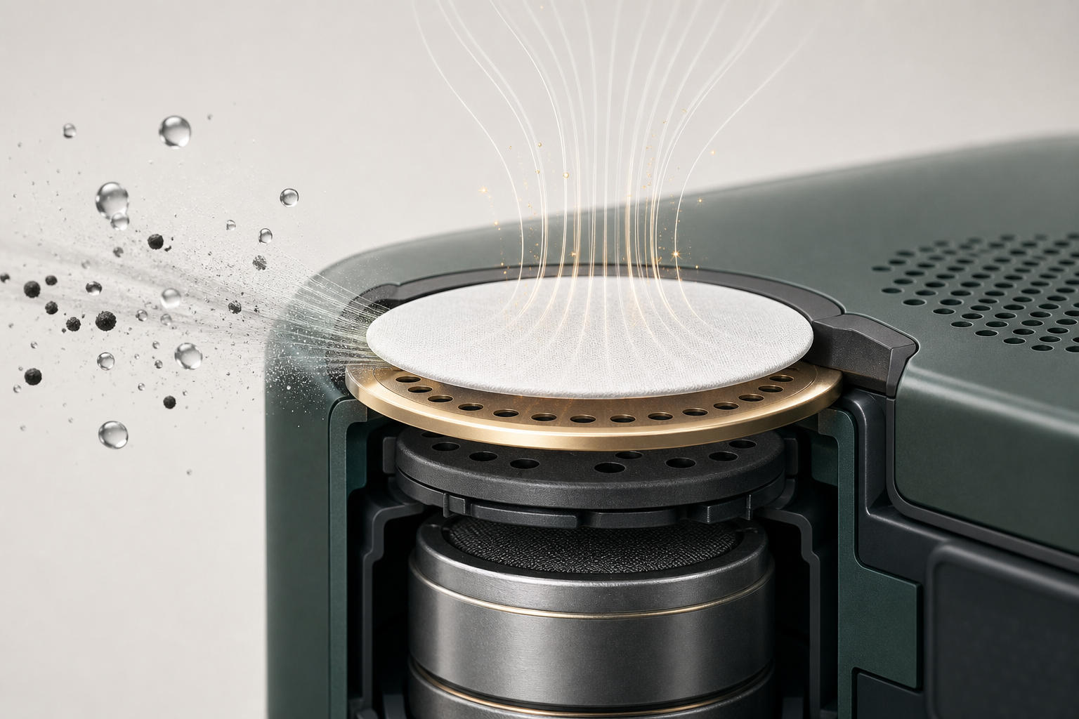
A multidisciplinary view of acoustic compliance, porous membranes, vent geometry and real product design
A waterproof membrane cannot physically increase the volume of a speaker enclosure. A 0.5 cc rear cavity is still 0.5 cc after a membrane is added.
Yet in miniature acoustic systems, a properly designed vent can reduce the acoustic stiffness seen by the driver and make a small rear cavity behave, over part of the frequency range, more like a larger one.
This effect is sometimes described as a virtual increase in rear-cavity volume. The interesting part is that this is not purely an acoustics problem. It involves acoustics, porous materials, fluid motion, mechanical geometry, manufacturing tolerances and long-term reliability.
So what is actually happening?
1. Start with the Air Trapped Behind the Speaker
In a sealed rear cavity, the air behaves like a spring. When the diaphragm moves inward, the air is compressed. When the diaphragm moves outward, it expands.
The acoustic compliance of the cavity can be approximated by:
Cₐ = V / (ρc²)
Here V is cavity volume, ρ is air density and c is the speed of sound. The smaller the cavity, the lower its compliance and the stiffer the air spring becomes.
This matters increasingly in products such as smart glasses, TWS earbuds, smartwatches, hearing devices, miniature speakers and compact cameras.
In these products, every cubic millimeter may already be competing with the battery, PCB, antenna, optical module and mechanical structure. The acoustic engineer may want more rear volume. The mechanical engineer may simply have nowhere to put it.
2. Now Give That Cavity a Controlled Pressure-Relief Path
Consider adding a vent to the rear cavity:
Driver → Rear cavity → Vent opening → Membrane → Ambient
The cavity is no longer perfectly sealed. But it is also not simply open. The vent has an acoustic impedance. A useful first-order representation is:
Zᵥ(ω) = Rᵥ + jωMᵥ
Rᵥ represents the resistive part of the vent. Mᵥ represents the acoustic mass of the air moving through the vent path.
The rear cavity now sees two possible acoustic paths: one through the compressed cavity air, and another through the vent. Conceptually:
Zrear = Zcavity ∥ Zvent
This changes the load seen by the diaphragm. At frequencies where pressure can relax through the vent, the air spring becomes effectively softer. And a softer air spring is exactly what we would normally obtain by making the physical rear cavity larger.
That is the origin of the “virtual volume” idea. But there is an important limitation: the effect is frequency dependent. The membrane does not magically turn 0.5 cc into 1.0 cc at every frequency.
3. This Is Where Material Science Enters the Problem
The vent impedance is not determined by geometry alone. For an ePTFE membrane, the gas moves through a three-dimensional microporous network consisting of nodes, fibrils and interconnected tortuous pathways.
Several material parameters therefore matter:
- Pore-size distribution
- Porosity
- Tortuosity
- Membrane thickness
- Fibril structure
- Surface chemistry
- Hydrophobic or oleophobic treatment
These properties influence how easily oscillating air can move through the material. At low-frequency or slowly changing pressure conditions, air has more time to redistribute through the pores. As frequency increases, viscous interaction with the pore walls and the inertia of the moving air become increasingly important.
The membrane therefore behaves less like a simple hole and more like a frequency-dependent porous acoustic element. The waterproof membrane is not just preventing water from entering the product. Its microstructure is participating in the acoustic loading of the driver.
4. Mechanical Design Can Change the Effect as Much as the Membrane
Even with exactly the same membrane, the vent can behave very differently after integration into the product. A small opening contains moving air, and that air has acoustic mass.
A simplified relationship is:
Mₐ ≈ ρLeff / A
A is the effective opening area. Leff is the effective acoustic path length.
Smaller opening → larger acoustic mass. Longer vent path → larger acoustic mass.
The effective path is not determined only by the housing. It may also include housing wall thickness, adhesive thickness, adhesive inner diameter, support layer, membrane position and protective grille.
A mechanical change that looks very small on a drawing can materially change the acoustic behavior. For example, changing an adhesive ID from 2.0 mm to 1.5 mm is not simply reducing the vent area by 25%. Because area scales with diameter squared, the effective acoustic area changes much more strongly.
That changes the airflow velocity and acoustic mass of the vent path. This is why the vent should be treated as an acoustic component, not merely as a waterproof hole.
5. The Membrane Can Also Control Resonance and Q
Once the driver, rear-cavity compliance and vent impedance interact, the system develops its own resonance behavior.
A completely sealed small cavity may add significant stiffness to the driver. Opening the cavity too much can reduce that stiffness, but may also change the driver loading more than intended. A resistive membrane creates an intermediate condition.
- Very high vent resistance → cavity behaves close to sealed
- Controlled vent resistance → pressure relaxation + useful damping
- Very low vent resistance → cavity becomes strongly coupled to ambient
The resistive part of the membrane can therefore influence system damping and resonance Q. This is closely related to the idea behind resistively vented or aperiodic loudspeaker enclosures.
The goal is not always to remove the resonance. Sometimes the goal is to control it. A suitable vent may reduce an excessive resonance peak, change system Q, reduce effective rear-cavity stiffness, alter diaphragm loading and improve pressure equalization.
The lowest-resistance membrane is not necessarily the best acoustic membrane. The correct vent impedance depends on the driver and enclosure around it.
6. Manufacturing Determines Whether the Designed Acoustic Impedance Actually Exists
On paper, we may define membrane impedance, opening diameter, cavity volume and vent path length. But the production part does not always look exactly like the CAD model.
Real variation can come from:
- Die-cutting tolerance
- Adhesive ID tolerance
- Membrane wrinkling
- Adhesive flow
- Placement eccentricity
- Lamination pressure
- Membrane tension
- Thermal processing
For a miniature vent, a shift of only a few tenths of a millimeter may significantly change the effective opening area. That means the acoustic network that exists in mass production can differ from the one used in simulation.
This is why acoustic tuning and manufacturing capability cannot be separated completely. A design that works beautifully on one laboratory sample but is extremely sensitive to a ±0.1 mm assembly variation may not be a robust design.
7. Reliability Adds Another Time Dimension
Will the vent have the same acoustic impedance after six months of real use?
Environmental exposure can change the system. Examples include humidity, sweat, oil contamination, dust, thermal cycling, steam exposure and adhesive aging.
For porous membranes, contamination or changes in surface wetting behavior may affect gas transport. For the adhesive structure, heat and humidity may change geometry or bond integrity.
So the acoustic tuning should not only work at T = 0. It should remain stable after environmental and reliability testing. That is especially important when the vent is being used not only for waterproofing, but also as part of the acoustic tuning strategy.
The Engineering Takeaway
The idea of “virtual rear-cavity expansion” is useful, but it should not be interpreted too literally. A waterproof vent does not create physical volume. Instead, it changes the way pressure inside the rear cavity can relax. That changes the effective acoustic stiffness and damping seen by the driver.
That effect emerges from the interaction of several disciplines:
- Acoustics determines cavity compliance and driver loading.
- Material science determines how the porous membrane resists oscillating airflow.
- Fluid mechanics governs pressure-driven flow through microscopic paths.
- Mechanical design defines opening area and acoustic path length.
- Manufacturing determines how closely the real part matches the intended geometry.
- Reliability engineering determines whether those properties remain stable over time.
The more useful design question is not “Which membrane has the lowest sound loss?” but “What vent impedance does this driver and rear cavity actually need?”
Once a waterproof membrane is connected to a speaker cavity, it is no longer only a barrier against water. It becomes part of the acoustic system.